Solar System Engineering Process: A Professional's Guide
Solar System Engineering Process: A Professional’s Guide

Solar system engineering is the multidisciplinary design, analysis, and planning process that takes a solar energy project from concept to a fully operational, code-compliant installation. It is not simply placing panels on a roof. The process draws on electrical, structural, civil, mechanical, and regulatory engineering disciplines working in concert to produce a system that is safe, efficient, and financially sound.
The core deliverables of solar project development include:
- System sizing and load analysis based on site-specific peak sun hours and energy demand
- Component selection covering panels, inverters, and battery storage
- Electrical and structural design addressing wiring, mounting, and wind or snow load calculations
- Permitting and code compliance documentation for the Authority Having Jurisdiction (AHJ)
- Utility interconnection coordination to secure Permission to Operate (PTO)
- An implementation roadmap that sequences construction, inspection, and commissioning
Every one of these elements depends on the others. Miss the load analysis and the system is undersized. Skip the structural review and the permit gets rejected. The process works because it is sequential and integrated, not because any single step is clever on its own.
What are the key stages of the solar system engineering process?
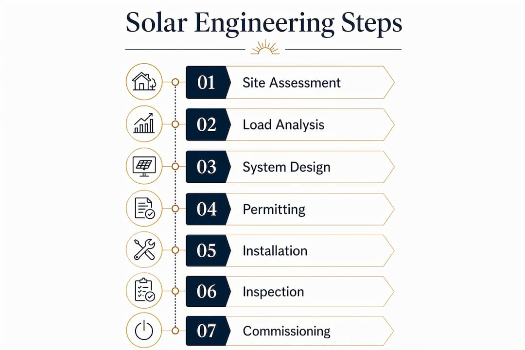
The steps in solar engineering follow a defined sequence, though real projects loop back through earlier stages as new data arrives.
-
Site assessment. Engineers evaluate solar irradiance, shading from trees or adjacent structures, roof orientation, and topography. Tools like PVWatts provide an initial energy baseline using location-specific Global Horizontal Irradiance (GHI) data.
-
Load estimation and system sizing. Daily kilowatt-hour consumption and peak sun hours for the site determine required array capacity. The formula is straightforward: array kW equals energy required divided by the product of peak sun hours and system efficiency.
-
Electrical and structural design. String configuration, wire sizing, inverter placement, overcurrent protection, and mounting hardware are all specified here. Structural calculations must confirm the roof framing can carry the added dead load and wind uplift per ASCE 7 standards.
-
Energy modeling and simulation. Software tools model annual production, accounting for shading losses, inverter efficiency, and temperature derating. This output sets realistic client expectations before any equipment is purchased.
-
Permitting and plan set preparation. A complete residential permit package typically runs 8–12 sheets: site plan, roof layout, single-line diagram, three-line diagram, structural details, equipment schedule, rapid shutdown plan, and labeling schedule. NEC Article 690 governs the electrical design; NEC 690.12 specifically requires rapid shutdown compliance on all US rooftop systems.
-
Utility interconnection. The building permit and utility interconnection agreement are separate approvals. Both are mandatory before the system can legally operate.
-
Construction planning and commissioning. Installation sequencing, crew scheduling, equipment delivery, and final testing protocols are all mapped before work begins on the roof.
Pro Tip: Run a pre-submittal checklist against the AHJ’s published guidelines before every permit submission. The three most common rejection triggers are incorrect fire setbacks, incomplete single-line diagrams missing OCPD ratings, and structural calculations that do not address wind uplift.
How do customer needs shape the solar energy system design?

Effective solar system design balances financial and energy perspectives, and that balance starts with an accurate picture of what the client actually needs. The NABCEP PV Installation Professional Resource Guide is direct on this point: an accurate assessment of customer needs is the starting point for specifying, designing, and installing any PV system.
Key factors that shape the design conversation:
- Energy consumption profile. Monthly utility bills reveal usage patterns, not just totals. A household with heavy evening loads needs a battery storage strategy, not just a larger array.
- Financial priorities. Some clients want maximum offset; others want the shortest payback period. These goals produce different system configurations.
- Site constraints. Roof age, available area after fire setbacks, HOA restrictions, and shading all limit what is technically feasible.
- Regulatory requirements. NEM 3.0 in California, for example, changes the economics of oversizing an array without paired battery storage.
Penn State’s EME 810 course frames solar design as “pattern with a purpose”, meaning every design decision should serve the intersection of the solar resource, the client’s goals, and the project locale. Ignoring any one of those three produces a system that underperforms on at least one dimension.
Pro Tip: Model two or three system configurations before the client meeting, showing the tradeoffs between upfront cost, annual production, and payback period. Clients make better decisions when the numbers are in front of them, not described in the abstract.
Why is solar engineering an iterative process?
Solar engineering rarely moves in a straight line from concept to construction drawings. The design process evolves from an initial technical concept through successive refinements, with each phase feeding new constraints back into earlier decisions. That iteration is not inefficiency. It is how costly post-installation changes get caught on paper instead of on the roof.
Typical iterative checkpoints include:
- Technical validation. Does the proposed array size match the load analysis after applying real shading and temperature derating factors?
- Structural validation. Can the existing roof framing support the calculated dead load and wind uplift without reinforcement?
- Regulatory validation. Does the design meet the AHJ’s fire setback requirements and the utility’s interconnection technical standards?
- Financial validation. Does the final configuration still meet the client’s payback target after equipment costs are confirmed?
Each checkpoint can send the design back a stage. A structural finding that requires rafter sistering, for instance, changes the mounting layout, which changes the string configuration, which may require a different inverter. Working through these dependencies before permit submission is what separates a clean approval from a correction cycle.
How does permitting, inspection, and interconnection work in the US?
The PI&I process, covering permitting, inspection, and interconnection, is coordinated by the installer across two separate regulatory tracks: the local AHJ and the electric utility. Both approvals are mandatory before the system can be energized, and they run on independent timelines.
| Stage | Who Approves | Typical Timeline |
|---|---|---|
| Permit plan review (AHJ) | City or county building department | Same day to 6+ weeks |
| Authorization to build | AHJ issues after plan approval | Concurrent with above |
| System installation | Installer | 1–2 days on-site |
| Final inspection | AHJ inspector | Days to weeks after install |
| Utility interconnection (PTO) approval times vary and can extend several weeks after installation. |
A median residential permit takes 1–2 weeks for AHJ review, but timelines range from same-day approval in SolarAPP+ jurisdictions to more than 6 weeks in complex manual-review AHJs. The utility interconnection runs separately and can extend the gap between a completed installation and a live system by several additional weeks.
Common causes of permit delays include missing fire setback dimensions on the roof plan, single-line diagrams with unlabeled overcurrent protection devices, and structural calculations that do not address wind uplift. Jurisdictions using automated platforms like SolarAPP+ process compliant plan sets in minutes rather than weeks.
How do you select solar panels, inverters, and batteries?
Component selection follows directly from the load analysis and system design. Each category involves specific engineering tradeoffs.
Solar panels are evaluated on efficiency, temperature coefficient, degradation rate, and physical dimensions relative to available roof area. High-efficiency monocrystalline panels produce more power per square foot, which matters on constrained rooftops. Degradation rate affects long-term production modeling.
Inverters are the electrical core of the system. String inverters are standard for residential applications with unobstructed roof planes. Microinverters or DC optimizers perform better on roofs with partial shading or multiple orientations, because they isolate each panel’s output. The DC-to-AC overloading ratio, typically 1.2 to 1.5, is a key sizing parameter. Modern inverter technology reaches up to 98.5% peak efficiency, though real-world performance depends on operating conditions.
Battery storage adds NEC Article 706 compliance requirements and its own permit documentation. For home battery storage in a NEM 3.0 environment, battery selection directly affects the economics of the system. Options like the Tesla Powerwall, Enphase IQ Battery, and Franklin WH each have different usable capacity, continuous power output, and compatibility profiles with common inverter platforms.
How do engineers integrate and optimize a complete solar system?
System integration is where individual components become a functioning power plant. The goal is to minimize losses at every conversion and transfer point. Key techniques include:
- String configuration optimization. Matching string voltage to the inverter’s MPPT window across the full temperature range prevents clipping losses.
- Wire sizing and voltage drop. NEC calculations target voltage drop below 3% on AC runs. Undersized conductors waste production and generate heat.
- Shading mitigation. Module-level power electronics (MLPEs) limit the impact of partial shading on overall array output.
- Thermal management. Inverter placement in shaded, ventilated locations reduces thermal derating. Adequate clearance between modules and the roof surface also affects operating temperature and long-term output.
- Monitoring integration. Data logging and cloud-based monitoring platforms track real-time yield, flag underperformance, and support preventive maintenance decisions.
For additional technical context on solar integration practices, electrical contractors working across residential and commercial projects apply many of the same optimization principles regardless of system scale.
What does cost estimation look like for a solar project?
Accurate cost estimation requires itemizing every component and labor category before the project is sold. The major cost buckets in residential solar project development are:
- Equipment. Panels, inverter, racking, wiring, disconnects, and monitoring hardware.
- Battery storage. Adds material cost and increases permit complexity, pushing plan sets from 8–10 sheets to 12–14 sheets.
- Labor. Installation crew time, typically 1–2 days for residential systems, plus engineering and design hours.
- Permitting fees. AHJ permit fees for residential systems vary by jurisdiction and are charged as flat or valuation-based fees, though some jurisdictions use per-kW or valuation-based schedules.
- Utility interconnection. Application fees vary by utility.
- Soft costs. Site survey, system design, plan set preparation, PE stamp, and project management.
The 30% federal Investment Tax Credit applies to panels, battery storage, and installation costs, which meaningfully changes the net cost calculation for homeowners. Typical residential payback periods and electric bill reductions vary across installations and customer usage profiles.
What happens during solar system testing and commissioning?
Commissioning is the final engineering gate before a system goes live. It verifies that the physical installation matches the approved plan set and that every component performs within specification.
A standard commissioning sequence covers:
- Visual inspection. Confirm panel placement matches the approved roof layout, all conduit runs follow the permitted routing, and labeling is complete per NEC requirements.
- IV curve testing. Measures each string’s current-voltage output against the manufacturer’s specification to detect cell damage, wiring faults, or connection issues.
- Insulation resistance testing. Verifies DC wiring integrity before energizing the system.
- Rapid shutdown test. Confirms NEC 690.12 compliance by verifying the system de-energizes within 30 seconds of activation.
- Grid synchronization check. Confirms the inverter synchronizes correctly with utility voltage and frequency before export begins.
- Monitoring system verification. Validates that production data is logging correctly and accessible for ongoing performance tracking.
After the AHJ final inspection passes, the installer submits the inspection results to the utility, which then reviews and issues Permission to Operate. That PTO document is what legally allows the system to export power to the grid.
Ready to put the engineering process to work on your roof?

San Diego Solar has been engineering and installing residential solar systems in San Diego County since 1996, pulling the first commercial solar permit in the City of San Diego and completing thousands of installations with 100% in-house crews. Every system is custom designed by our in-house engineering team based on your actual roof, your utility bills, and your goals.
We handle the full solar system design process: site assessment, load analysis, permit plan sets, SDG&E interconnection, and HOA approvals. You get a written project timeline before you commit and manufacturer warranties up to 25 years.
Get your free consultation and see what three decades of solar engineering experience looks like on your roof.
Key Takeaways
The solar system engineering process succeeds when site assessment, iterative design, code-compliant permitting, and precise commissioning are treated as a single integrated workflow, not separate tasks.
| Point | Details |
|---|---|
| Multidisciplinary by design | Solar engineering spans electrical, structural, civil, mechanical, and regulatory disciplines working in sequence. |
| Permitting has two tracks | The AHJ building permit and utility interconnection agreement are separate approvals; both are required before operation. |
| Timelines vary widely | AHJ review ranges from same-day to 6+ weeks; utility PTO adds another 2–8 weeks after inspection. |
| Iteration reduces cost | Catching structural, electrical, and regulatory conflicts during design prevents expensive post-installation changes. |
| Client needs drive configuration | Energy usage profile, financial goals, and site constraints together determine the optimal system design, not panel count alone. |